
EMPATICA
Testing & Analysis
One of my primary tasks for my time at Empatica was to achieve a watertight seal up to 5 ATMs of pressure on the prototype device we were designing. To achieve this, I determined the amount of compression needed on the sealing rubber to create a reliable seal. Then, I tested to see if this amount of compression was possible using magnets.
Using 3D printed and laser cut fixtures and jigs, I was able to iteratively test different compression values under pressure and evaluated them to find the optimal combination. After compression testing, I moved on to maximizing the amount of magnetic attraction force between the two portions of the device, and seeing if this was enough to maintain a water-resistant seal. Using more 3D printed parts, I was able to test different magnets in different locations to maximize the amount of attraction force between the two parts. To see more information about these tests, click here!
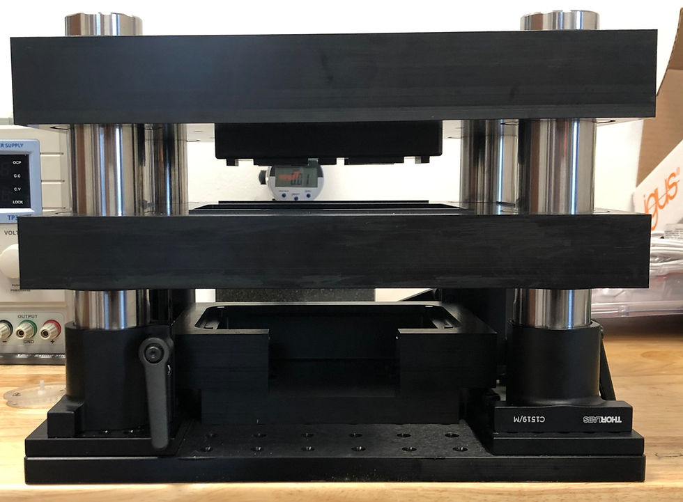
Jig used for water resistance compression testing.

Pod holder on top of the Integrating Sphere jig.
Jig Design & Fabrication
During my time at Empatica, I was tasked with helping the electrical engineering team in Milan quickly design and create any fixtures necessary to progress forward with development. Using a combination of CAD, laser cutting, and 3D printing, I was able to create most of the fixtures that the team needed and sent them to Milan within a few days.
To see more information about the projects I worked on, see below!
Bed of Nails
My final project at Empatica was to create a mechanically working end-of-line test machine called a Bed of Nails. This machine was able to test multiple PCB boards right off of the assembly line in order to make sure they are all functioning properly.
Using a combination of custom-designed and off-the-shelf parts, I was successfully able to design a mechanically working prototype of the machine. After designing the parts, I worked with machinists in China and had the parts fabricated and was then able to build the machine. To see more information about this project, click here!

Bed of Nails test machine.
Gallery Of Works
Click or highlight the picture for more information!

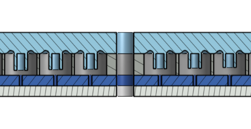
In this test, twelve rubber rings were placed inside small inlets in acrylic. A small piece of litmus paper was placed in the middle of each ring.

A cap with extrusions resembling the interfacing seals on our prototype was placed on top, compressing the rubber rings seated beneath them. Each extrusion extended out at a varying length, resulting in varying amounts of compression on each ring.
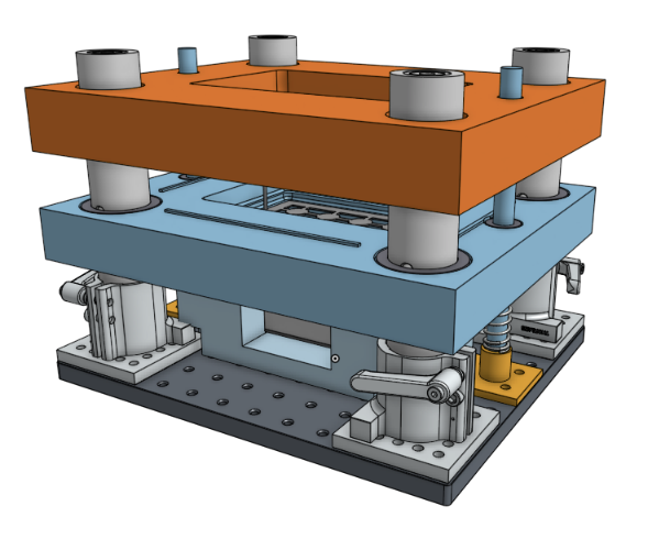
The 3D print of the second version of the compression test jig.
In this test, twelve rubber rings were placed inside small inlets in acrylic. A small piece of litmus paper was placed in the middle of each ring.

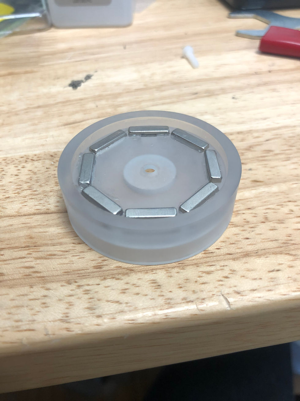
The goal of this test was to see if we could achieve adequate compression on our sealing rubber using magnets. Different magnet locations around the prototype were tested in order to determine the best orientation of magnets to get the most amount of attraction force.
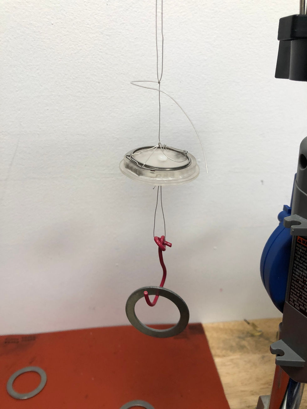
To do this, I suspended this fixture, and hung weights off the bottom until the fixture detached from the metal ring. The weight it held before detaching was recorded, and the magnets were moved to a new location. The results from each test were analyzed and the best magnet location was determined.
Finally, to validate my solution, I created another jig and re-ran the test. While the bar magnets did improve the total amount of attraction force, we determined that magnets alone were not enough to fully compress the rubber, so we looked towards alternate, mechanically driven solutions.
The goal of this test was to see if we could achieve adequate compression on our sealing rubber using magnets. Different magnet locations around the prototype were tested in order to determine the best orientation of magnets to get the most amount of attraction force.
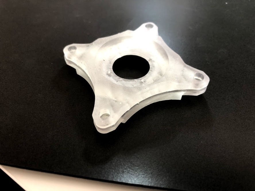
To speed up testing in Milan, I designed and fabricated a fixture to hold our prototype device for the electrical team. Also, I created a jig to be able to attach the fixture to an Integrating Sphere, so the team could test the sensors in the device.
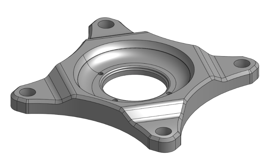
CAD for the Pod holder.
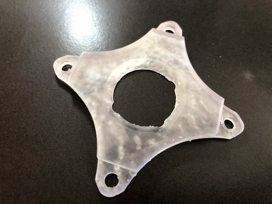
The 3D print of the I.S. jig. This was also sent to Milan.
To speed up testing in Milan, I designed and fabricated a fixture to hold our prototype device for the electrical team. Also, I created a jig to be able to attach the fixture to an Integrating Sphere, so the team could test the sensors in the device.

To properly test the accelerometers in the device, the electrical needed a fixture to hold the prototype at different angles. Using these two jigs, the team could test the accelerometers functionality at multiple different angles in the device.
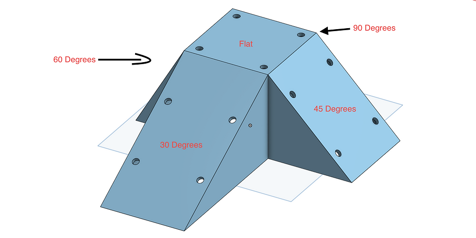
This is the CAD of the first prototype I designed. While this would have encompassed every angle necessary, there was a lot of unnecessary material being used to create it, making them expensive to print. I was able to split them into two separate parts, ultimately using a lot less material.

CAD of the second pyramid jig.
To properly test the accelerometers in the device, the electrical needed a fixture to hold the prototype at different angles. Using these two jigs, the team could test the accelerometers functionality at multiple different angles in the device.
My final project at Empatica was to create an end of line test machine called a Bed of Nails. This machine can test sheets of PCBs right after they are assembled to ensure they are all functioning properly.
I started this project by importing off-the-shelf parts into CAD, allowing me to build around them. Then, while working with a manufacturer, I designed any necessary parts, and sent the designs to China to be machined.

The full, mechanically working assembly.
My final project at Empatica was to create an end of line test machine called a Bed of Nails. This machine can test sheets of PCBs right after they are assembled to ensure they are all functioning properly.
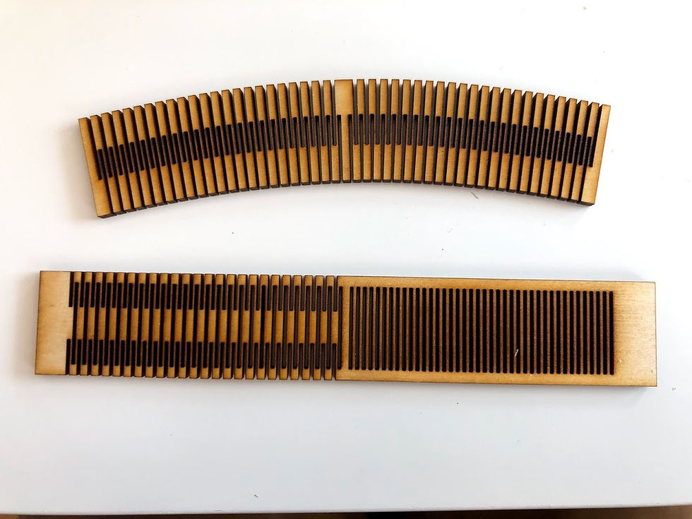
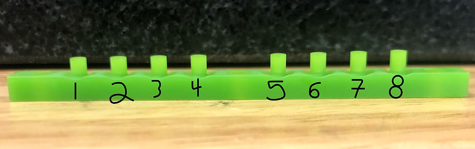
To test how different cut patterns can influence bend radius, I laser cut this wood sample. Using this, I was able to visualize how this may affect rubber if cut in a similar fashion.

The CAD model used to laser cut the wood.

A photo depicting woods ability to bend with a relatively small bend radius.
To test how different cut patterns can influence bend radius, I laser cut this wood sample. Using this, I was able to visualize how this may affect rubber if cut in a similar fashion.

While at Empatica, I was a member at the Fablab@CIC and had access to various 3D printers and laser cutters. While working there, I noticed the 3DWOX printer was malfunctioning, resulting in frequent misaligned layers. One of the clips holding the tray to the bottom was missing, so I emailed the company, got the .STL files for the attachment assembly, and printed a new part. The new part locked the tray in properly, fixing the problem I was facing.
Here is an example of a part with misalligned layers.

After replacing the first mechanism, I printed another and replaced the other old one to ensure the printer would be usable for the foreseeable future.
While at Empatica, I was a member at the Fablab@CIC and had access to various 3D printers and laser cutters. While working there, I noticed the 3DWOX printer was malfunctioning, resulting in frequent misaligned layers. One of the clips holding the tray to the bottom was missing, so I emailed the company, got the .STL files for the attachment assembly, and printed a new part. The new part locked the tray in properly, fixing the problem I was facing.

One of my first tasks given to me at Empatica was to come up with a way to repetitively twist and turn a wrist strap in multiple directions to simulate wear over time. Using a step-motor, an Arduino, and a custom-designed strap holding fixture, I was able to create an automated strap testing machine which could simulate wear in multiple directions.

3D print of the strap fixture used in the strap testing machine.
One of my first tasks given to me at Empatica was to come up with a way to repetitively twist and turn a wrist strap in multiple directions to simulate wear over time. Using a step-motor, an Arduino, and a custom-designed strap holding fixture, I was able to create an automated strap testing machine which could simulate wear in multiple directions.